7.相关产品
产品概述 返回TOP
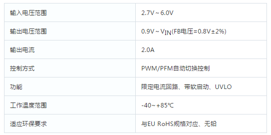
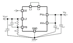
CXDC65114系列产品是把线圈和控制IC组成一体的超小型(3.1mm×4.7mm, h=1.3mm)降压DC/DC转换器。通过将线圈内置在封装组件内,使得电路板布局更为简单,可以把因电路布线的经络而引起的错误动作或噪声等抑制在最小限度。输入电压范围在2.7V~6.0V之间。输出电压可用电阻从0.9V任意设定。CXDC65114通过在轻负载时降低工作频率,实现了从轻负载到重负载整个区域内的高效率。软启动时间设定为1ms(TYP.),可以使输出电压高速启动。限定电流功能被设定为4.0A(TYP.)。内置了UVLO(Under VoltageLock Out)功能,当输入电压在2.4V(TYP.)以下时,强制停止内部驱动晶体管工作。当CE=Low时,利用CL放电功能将CL(负载电容)中的电荷放电,将消耗电流抑制在1.0μA以下。
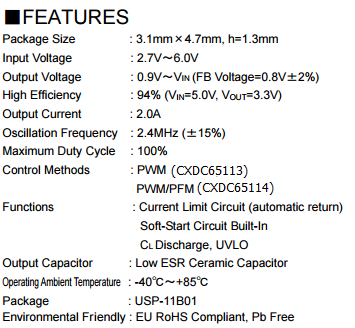
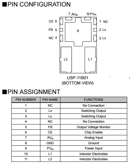
The CXDC65113/CXDC65114series is a synchronous step-down micro DC/DC converter which integrates an inductor and a control IC in one tiny package (3.1mm×4.7mm, h=1.3mm). An internal coil simplifies the circuit and enables minimization of noise and other operational trouble due to the circuit wiring. A wide operating voltage range of 2.7V to 6.0V enables support for applications that require an externally set output voltage can be selected. The CXDC65113/CXDC65114 series uses synchronous rectification at an operating frequency of 2.4MHz. PWM control (CXDC65113) or automatic PWM/PFM switching control (CXDC65114) can be selected. The CXDC65113 series has a fixed frequency, enabling the suppression of output ripple. The CXDC65114 series achieves high efficiency while holding down output ripple across the full range of loads, from light to heavy, enabling the extension of battery operation time. The series have a high speed soft-start as fast as 1ms in typical for quick turn-on. With the built-in UVLO (Under Voltage Lock Out) function, the internal P-channel driver transistor is forced OFF when input voltage becomes 2.4V or lower. It’s suitable for large-current application due to limit current is configured 4.0A in typical. The integrated CL discharge function which enables the electric charge at the output capacitor CL to be discharged via the internal discharge switch located between the LX and GND pins. Due to CL discharge function, malfunction on LX is prevented when Stand-by mode
产品特点 返回TOP


应用范围 返回TOP
●Note PCs
●Printers
●Tablet PCs
●PND(Portable Navigation Device)
技术规格书(产品PDF) 返回TOP
需要详细的PDF规格书请扫一扫微信联系我们,还可以获得免费样品以及技术支持!

产品封装图 返回TOP

电路原理图 返回TOP

|
线圈一体型DC/DC转换器 |
||||||||||||
|
产品名称 |
封装 |
类型 |
控制 |
FET |
VIN (MIN) (V) |
VIN MAX |
VOUT MIN V |
VOUT MAX V |
IOUTorIIN mA |
FB/VOUT 电压精度 (%) |
振荡频率 (MHz) |
消耗电流 (μA) |
|
cl2025 |
StepUP |
PFM |
Nch FET |
0.9 |
5.5 |
2 |
5 |
100 |
±2.0 |
1.2 |
6.3 |
|
|
cl2025-02 |
升压 |
PWM |
Nch FET |
0.9 |
6 |
2 |
5.5 |
500mA@VOUT=5.0V, VBAT=3.3V(TYP.) 350mA@VOUT=3.3V, VBAT=1.8V(TYP.) |
±2.0 |
3 |
||
|
cl2025-02 |
升压 |
Auto PWM/PFM |
Nch FET |
0.9 |
6 |
2 |
5.5 |
500mA@VOUT=5.0V, VBAT=3.3V(TYP.) VBAT=1.8V(TYP.) |
±2.0 |
3 |
||
|
cl2025 |
StepDown |
PWM |
Nch FET |
2 |
6 |
1 |
4 |
400 |
±2.0 |
1.2 |
22 |
|
|
cl2025 |
StepDown |
PWM PFM |
Nch FET |
2 |
6 |
1 |
4 |
400 |
±2.0 |
1.2 |
22 |
|
|
cl2025 |
StepDown |
PWM |
Nch FET |
2 |
6 |
1 |
4 |
600 |
±2.0 |
3 |
46 |
|
|
cl2025 |
StepDown |
PWM/PFM |
Nch FET |
2 |
6 |
1 |
4 |
600 |
±2.0 |
3 |
21 |
|
|
cl2025 |
StepDown |
PWM/PFM 外部转换 |
Nch FET |
2 |
6 |
1 |
4 |
600 |
±2.0 |
3 |
21 |
|
|
usp10b03 |
StepDown |
PWM |
Nch FET |
1.8 |
6 |
1 |
4 |
400 |
±2.0 |
3 |
46 |
|
|
usp10b03 |
StepDown |
PWM PFM |
Nch FET |
1.8 |
6 |
1 |
4 |
400 |
±2.0 |
3 |
21 |
|
|
cl2025-02 |
StepDown |
PFM |
Nch FET |
2 |
6 |
1 |
4 |
200 |
±2.0 |
3 |
0.5 |
|
|
usp11b01 |
StepDown |
PWM |
Nch FET |
2.7 |
6 |
1 |
VIN |
2000 |
±2.0 |
2.4 |
53 |
|
|
usp11b01 |
StepDown |
PWM PFM |
Nch FET |
2.7 |
6 |
1 |
VIN |
2000 |
±2.0 |
2.4 |
53 |
|
|
usp9b01 |
StepDown |
PWM |
Nch FET |
2.7 |
5.5 |
1 |
3.6 |
1500 |
±2.0 |
3 |
400 |
|
|
usp9b01 |
StepDown |
PWM PFM |
Nch FET |
2.7 |
5.5 |
1 |
3.6 |
1500 |
±2.0 |
3 |
25 |
|
|
cl2025-02 |
StepDown |
PWM |
Nch FET |
2.5 |
5.5 |
1 |
3.6 |
1000 |
3 |
400 |
||
|
cl2025-02 |
StepDown |
PWM PFM |
Nch FET Pch FET |
2.5 |
5.5 |
1 |
3.6 |
1000 |
3 |
40 |
||
|
cl2025-02 |
StepDown |
PWM |
Nch FET |
2.5 |
5.5 |
1 |
3.6 |
500 |
1.2 |
250 |
||
|
cl2025-02 |
StepDown |
PWM/PFM |
Nch FET |
2.5 |
5.5 |
1 |
3.6 |
500 |
1.2 |
1 |
||